Looking for feedback on REC 1Q BMS Settings for 24V CALB LFP Starter Battery with Wakespeed, Cerbo GX
-
Hi everyone,
I've set up and have been using successfully for 1 1/2 years with no issues a REC Q BMS (firmware 1Q-4000+, manual rev 2.9.0 Jan 2023) for my 24V CALB 230 cells LiFePO4 battery bank (480Ah capacity, 16 matched cells in 2P8S configuration) as a dedicated starter battery for my Perkins diesel engine on a sailboat.
The system includes a Wakespeed WS500 alternator regulator (configured to have a minimum field drive of 3% to provide a signal for the tach—at 3% there is no battery charging), Victron Cerbo GX for monitoring/integration via CAN.
The duty cycle is primarily as a start battery: high cranking draw (~1000A) for 1-2 seconds during engine starts, followed by engine electrics/electronics loads, though the current draw when running the engine does not exceed 10 amps—in fact, there is almost no draw once the battery has been recharged as the engine is not electronically controlled but is an older style with mechanical controls and only some minimal relays.
When the battery is fully charged, the current draw is <1 amp. The vast majority of the time outside of cranking, there's only minimal parasitic draw (~0.3A from the REC-BMS 1Q, pre-charge module, Wi-Fi module, and Cerbo GX) when idle.
I'd love feedback on these recommended settings (from an experienced source—see table below).
I'm particularly curious what Ben, Rick or others with a lot of REC/Victron/marine LFP experience think—does this look optimal for a starter application to maximize longevity while ensuring reliable cranking and alternator charging? Any tweaks for better ESS #3 handling or float behavior?
Regarding ESS #3: This message shows up on the Cerbo GX and does not appear to be an error message, but so far the only way I've been able to clear it so that the REC-BMS will re-enable charging is to power cycle the REC 1Q. I'm trying to figure out if some of my settings need to be tweaked so that the REC enables charging again automatically.
Thanks in advance for any insights—especially from those with similar starter setups!
Note: This setup was designed by a very experienced electrical engineer who's successfully used CALB matched cells for starting all manner of diesel engines and generators in RVs and multiple boat projects. The CALB specs support high C-rate draws (up to 3C continuous, 10C peak) without issue, and it's performed flawlessly in similar installs—no voltage sag or cold cranking problems. My peak load is only 2C.
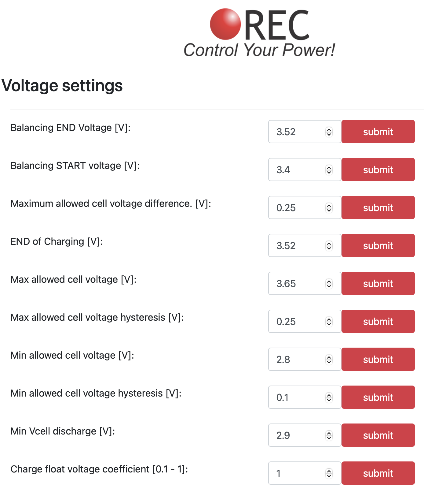
Here's my current settings table for reference:
Parameter
Value
Notes
Balancing END Voltage [V]
3.52
Per Ben's suggestion for float at 26.8V.
Balancing START Voltage [V]
3.45
Starts balancing above this.
Maximum Allowed Cell Voltage Difference [V]
0.25
Triggers balancing if exceeded.
END of Charging [V]
3.52
End of charge voltage per cell.
END of Charging Voltage Hysteresis per Cell [V]
0.17
Hysteresis for recharge trigger (results in ~26.8V float with CFVC=1).
Max Allowed Cell Voltage [V]
3.65
Over-voltage protection cutoff.
Max Allowed Cell Voltage Hysteresis [V]
0.15
Hysteresis for over-voltage reset.
Min Allowed Cell Voltage [V]
2.8
Under-voltage protection cutoff.
Min Allowed Cell Voltage Hysteresis [V]
0.05
Hysteresis for under-voltage reset.
Min Vcell Discharge [V]
2.9
Minimum cell voltage sent to inverter/CAN.
Charge Float Voltage Coefficient [0.1-1]
1
Allows 50% max current in float for loads; considering 0.8 default for comparison.
Charge Coefficient (CHAC) [1/h]
0.6
C-rate for max charging current calculation.
Battery Capacity (CAPA) [Ah]
480
Total pack capacity.
Maximum Charging Current per Device (MAXC) [A]
345
Per inverter/charger device limit.
Number of Inverter/Charger Devices (SISN)
3
Even though there are no Victron devices in the system, I said 3 so that the max discharge = 3x345A= 1,035 so that the REC allows that much current to start the engine.
Calculated max charging current: min(0.6 × 480 = 288A, 345 × 3 = 1035A) = 288A.
-
-
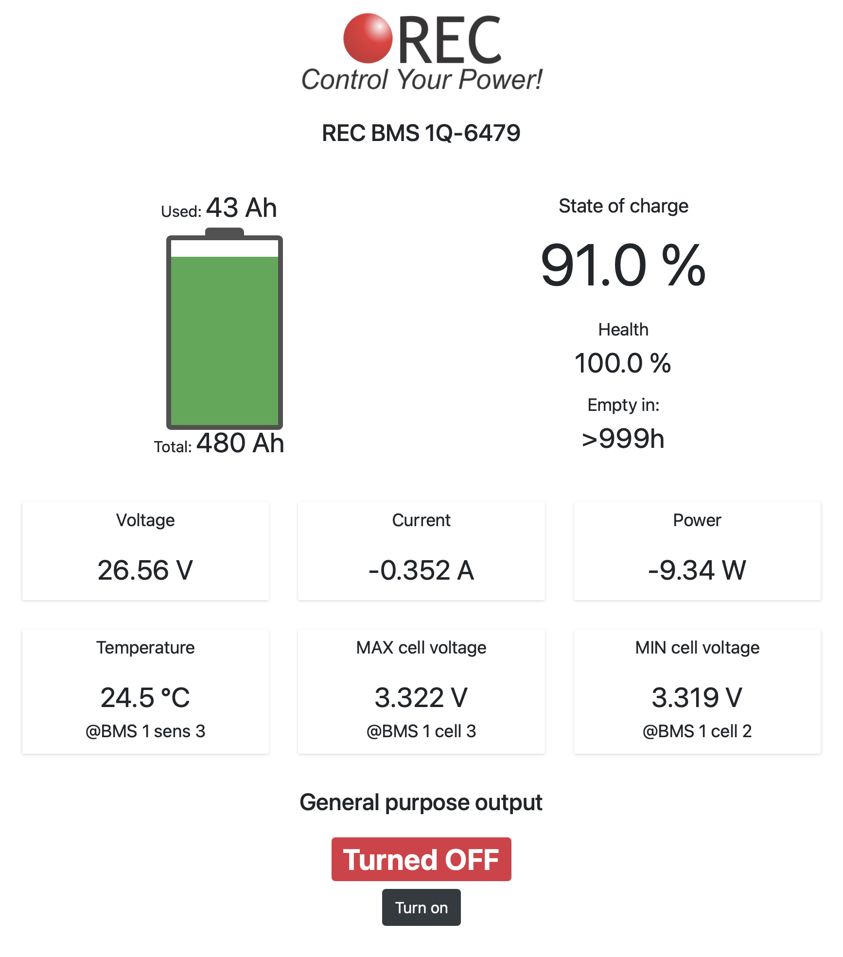
Hey Ben, thanks for the reply. Here is a screenshot of my REC home page. This is a 24V start battery, so 2x13.36=26.72. My SOCH = 0.05. Cell difference is typically 3-7mV. I have about 0.3A of drain from the various Victron and REC gear. I will keep a close eye on the behavior today. We are about to go on an overnight sail.