Usage of Relays and or Optocouplers - 9M Master with 3 * REC2Q Slaves - drive 6 contactors through 6 REC Pre-Charge Unit
-
Use of Relays and Opto-Couplers in Master-Slave configuration:
Dear community. I have written my questions also to Tine at REC headquarters but he is out of office until at least 1st of June.So I hope that someone can help me with my setup.
Any input is highly welcome.
I install my system in a boat and want to cross oceans with it. So I need a lot of redundancy and that is the reason why I have designed my system this way.
So I have 3 * 12V LiFePo4 (Winston 400 AH) battery banks. Each bank has it's own shunt, Class-T fuse, ML-RBS7700 contactor, REC Pre-Charge Unit (to drive the ML-RBS) and it's own REC 2Q Slave.
After the ML-RBS contactor each battery is connected to a battery bus (positive). After the battery bus the 'system side' is split into a Charge-bus and a Load-bus.
The idea is: If for example only 1 cell in one battery is going bad (too hot or over- under voltage) or there is too much imbalance in only 1 of the 3 battery banks, then the 2Q slave of this battery only opens the contactor of this 1 battery and the system remains working with the other 2 batteries. I can then investigate the cause and maybe just replace this one bad cell.
The reason to split my system into a Load bus and a Charge bus:
If for example 1 charge source (for example 1 of 8 MPPT chargers) has a fault and introduces a too high voltage, the Master 9M can open the contactor of the charge bus. Then I can still discharge my batteries while I isolate and repair the faulty equipment. The other way around: When the batteries hit the low voltage disconnect threshold, the 9M Master would open the contactor for the Load bus but I am still able to charge the batteries again. Normally nothing of this should be necessary as long as the Cerbo controls everything correctly via DVCC. It's just another layer of safety and redundancy.
I have drawn a little sketch of my system leaving all unnecessary parts out.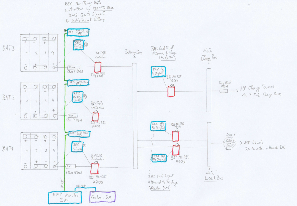
So I am using 6 * REC Pre-Charge Units to drive their dedicated ML-RBS7700 contactors. The 3 REC Pre-Charge Units of each battery before the Battery bus should be controlled by the REC 2Q slave of each battery in case only 1 battery has a problem. The 3 REC Pre-Charge units of the Charge- and Load buses (Charge bus 1 Pre-Charge unit and Load bus 2 Pre-Charge units) should be controlled by the REC 9M Master in case of system-wide problems in either the Charge- or the Load bus. I have wired all REC Pre-Charge units like they were designed by REC. So I need a BMS GND signal for each Pre-Charge unit to switch the contactors on.
I really need your help and advice here. How I can I control my system with the relays and optocouplers available in the Master9M and 2Q Slaves ?
Rec 2Q Slave:
In the REC manual I found the table with the REC 2Q Slave I O: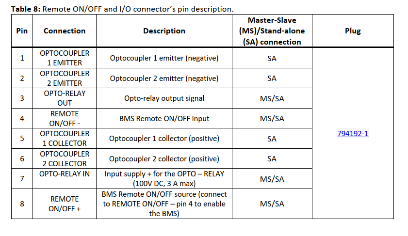
Does this mean that I can only use the Opto-relay (Pins 3 and 7) on the REC 2Q Slave in a Master-Slave configuration ?
Or is there also the possibility to use the Optocouplers ?
As I need a GND signal to control the Pre-Charge Unit: Can I also connect GND to Pin 7 and pass that GND via Pin 3 to the Pre-Charge Unit ?
Is this Opto-Relay NO (normally open) or NC (normally closed) ? I think I can control this via the 'Tasks' function over the WiFi-Module and also invert the function. Is that right ?
Relays on REC Master 9M:
In the REC manual I found this table: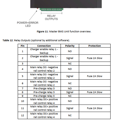
The manual says: "optional by additional software".
Does that mean that all relays are programmed according to the table and I can only change their function with a new firmware which REC would have to do for me ?
Or can I program these relays also via the 'Task' function over the Wi-Fi Unit ?
When charging via my generator I use 3 * VE Skylla IP65 chargers. Although they have VE.CAN they are not controlled via DVCC unfortunately. So I have to control them via the REC BMS and the remote High or Low signal of these chargers.
Can I use Relay 1 for this ? What does 'backup' mean for the Relay 1 ? Why is there a dash ( - ) in line 3 of the table ? If I want to use the L input of the Skylla IP65... Could I wire GND to Pin 2 and pass it through pin 3 (NC) to the L input of the Skylla IP65 ?
Could REC program this relay so that it switches off at a system SOC of 90 % ?
I will not need 'Main relay DC- negative rail control relay 2' as I have no contactors in the negative system side. Only shunts there.
Also I will not need relay 3 as all pre-charge functionality is handled by the 6 REC Pre-Charge Units.
So could I use relays 2, 3 and 4 to control the contactors of my load bus and my charge bus via their Pre-Charge Units and the BMS GND signal ?
What conditions could be programmed there ? In general I want an 'Allowed to Charge Function' and an 'Allowed to Discharge Function' so I would need 2 of the relays for these functions.
Would it be possible to use the remaining relay to switch off the inverters before the load bus main relay opens in a pre- alarm condition ?As already mentioned. Every input or help pointing me in the right direction is highly welcome.
A complete re-design of my system is not feasible as almost everything is already installed in tight spaces and I really need that redundancy, which made me choose the REC Master-Slave system in the first place.
Have a great day everyone.
Kind regards.
Martin Erlebach
(SY Catapulte)